| www.belightsoft.com/liveinterior | Start of Help | Index > Working with Objects |
Walls are the basis of your project. Usually you begin creating a floor plan by drawing external and then internal walls.
Walls can be of different types. Below are described the Storey Walls (general type of walls). Most of information here is also applicable to Loft Walls. To verify or change the wall type, go to the Object Properties tab of the Inspector. Walls of different types cannot join.
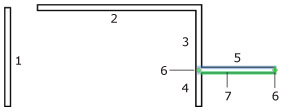
A wall segment is a piece of a wall that is limited by two end points. When the segment is selected, the end points (ends) are marked by green dots - handles (6).
If you draw a wall segment that crosses another one, both segments will split into two smaller segments.
If a segment joins another one in the middle, the latter will split into two smaller segments.
The program can join two segments of a straight wall into one when you remove the wall that crosses and splits it.
1–5 – Wall segments.
3 and 4 – These are parts of a single segment that has been divided into two parts by joining the 5th segment.
6 – Handles (green dots) of the 5th segment.
7 – The highlighted side (green) of the 5th wall segment. This indicates that this side will change if you modify wall properties in the Inspector (mouldings or materials).
The word “wall” is used in the program documentation both for a single wall segment and for a wall consisting of multiple wall segments if the number of segments does not matter.
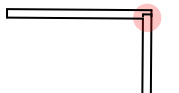 When you are creating a room, wall segments should join (like segments 2 and 3, or like 3, 4 and 5) to form a closed shape. The joint may break when you resize, move or add wall segments. Places where segments are joined incorrectly are marked by red circles on the floor plan. You should move a segment aside and then return it back to restore the connection. If this doesn't help, delete the affected segments and add them again.
To add a single wall segment:

To draw a rectangular room:
When you draw, the program snaps the mouse pointer to help you align the wall with other objects or to draw your line in the straight horizontal or vertical direction in the 2D view.
To stop drawing an unfinished wall segment, press the Esc key.
To remove a wall, select it and press the Backspace key.
To select a single wall segment, click on it with the mouse.
To select several segments, click on each of them while holding down the Shift key, or draw the selection frame over them.
All the wall segments used in the layout are listed in the Project Tree. You can use this list to select all the walls together.
When you move the mouse pointer over the selected wall, the pointer changes to:
If a wall segment has a free end (which does not make a corner with another segment), you can drag it with the mouse to resize the wall or to change its direction.
When you move a segment with two ends joining other segments, the program will change the length of these segments to keep the walls joined. So, the room will be reshaped. To rip a wall segment out, drag it holding the Option key.
To move walls without changing their size and direction, you should select and move all the joined segments together.
The Information bar displays the wall length, thickness and angle. The bar is located above the horizontal ruler at the top of the window. To toggle (show/hide) the ruler together with the Information bar, use the Show/Hide Rulers command in the View menu.
Most of the wall parameters can be modified in the Inspector window.
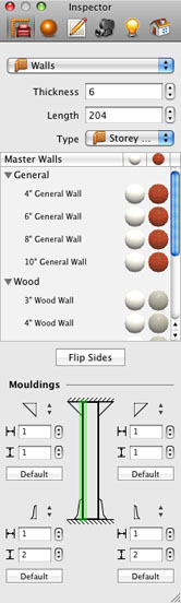
The set of tools in the Inspector window allows you to adjust the thickness and length of the selected wall. You can also choose the shape and size of the wall bases and wall crowns in the Mouldings section.
To change the shape of a crown or a base, use the corresponding drop-down list. If the wall should have no crown or base, select the “–” item. You can also change the width and height of the selected crown or base.
The Flip Sides button swaps the materials, wall crowns and wall bases on the sides of the wall.
The Master Walls box contains wall templates with predefined thickness and materials.
The Project Tree lets you control the Visibility and Lock options.
Making a wall invisible lets you take a picture of the 3D view from a greater distance. You can take a picture from outside the room to encompass more objects in the picture.
To change the length of a wall, select it and drag its handle with the mouse. Alternatively, you can use the Object Properties tab of the Inspector window.
The thickness can be set directly in the Object Properties tab, or you can select a predefined wall type from the Master Walls box in the Inspector window. The walls from the Master Walls box come with preset thickness and materials. You can think of them as wall templates.
All the walls on a floor have the same height equal to the height of the storey. To change it, use the Building Properties tab in the Inspector.
You can make a wall look lower than the storey height. To do this, insert an opening into the top part of the wall.
The Mouldings section in the Object Properties tab of the Inspector window controls the wall crown, base and trim. You can change their length and thickness, as well as size and shape. Also, it allows you to remove a crown, base and trim from any side of the wall.
Selecting a particular side of the wall lets you see the mouldings on the side that will be changed.
To change the material of the crown, base or trim, select it in the Project Tree, and then select the material in the Inspector window. Another way is dragging a material onto the crown, base or trim.
Use the Materials tab of the Inspector to apply or change a material. See Applying Materials for more detail.
The end surfaces (butt-ends) of walls do not have independent materials, they use the same material as one of the wall sides.
You may want to make walls look differently in the 2D view depending on their material or thickness. To do this, use the 2D Properties tab of the Inspector window.
You can use the settings from the Drawing section to change the color of the wall outline and the fill of wall segments, as well as apply fill patterns.